
Updating my 2007 SR8 with a MoTeC ECU/GCU
I'm upgrading my SR8 to a MoTeC M150 GPRP (general purpose racing paddle shift) controller. I found that the gearbox controller (by Geartronics) was so old that the tuning software didn't work, and that the Life F88 ECU didn't talk to the AIM MXL, and that the fans weren't under ECU control, and that that the ECU didn't monitor oil pressure.
My car, I've found, is one of just a few cars with this particular set of equipment, with the dash, ECU, GCU, and chassis harnesses (looms to you Brits, lol), all the worse for wear over the decade+ since the car was new. The car literally has two sensors for nearly everything: one for the ECU, and one for the dash.
My original plan was to upgrade the GCU to a current spec controller, but that couldn't be done with the old ECU. Then I thought I'd upgrade the ECU to a current version, but that couldn't be done with the original engine loom. Several people within Radical have considered this state of affairs, and have said they would help with an upgrade kit, but months have now passed with no progress. I think the problem is just too hard without completely rewiring the whole car.
And so that's what I'm doing. The plan is as follows:
- Replace the Life ECU / Geartronics GCU with a MoTeC M150.
- Upgrade the car to drive by wire (DBW) using a Jenvey Actuator. The M150 will do throttle/gearbox control via DBW instead of a pneumatic blipper.
- Replace the wasted spark ignition with a coil on plug (COP) ignition using Bosch Motorsports coils.
- Replace the fuel injectors with Injector Dynamics 1050x injectors.
- Use PWM control for fuel pressure maintenance instead of a mechanical regulator.
I'll update this thread with status and pictures as this project unfolds. The current status is that I have the new ECU and actuator in hand. The injectors will be here tomorrow. The coils should be here this week. I have to get this done quickly before funds run out, lol!
Wow, that is a big job! I am looking forward to following your progress!
Charley
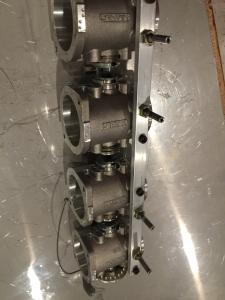
One of the first sub-tasks is to modify the throttle bodies to support a MAP (manifold absolute pressure, aka vacuum) sensor. There are no provisions for a vacuum port anywhere on them. Jenvey (the OEM) had no suggestions other than to ask Radical.
But the MoTeC needs a MAP for full function.
So off to add vacuum ports to each of the throttle bodies that can then be connected to a vacuum manifold (2 cubic inches to handle all eight TBs).
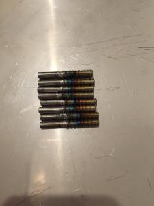
I eventually decided to replace one of the two bolts holding the TB to the alignment rail with a drilled bolt. In order to get a big enough hole, I needed a bigger bolt, so I drilled and tapped each one. You can see the bolt is bigger, and drilled all the way through.
Wow that is a great job...
Interesting what you were saying about your car having double sensors for everything. Our earlier SR3 00376 was set up the same way and also running the Life Racing F88 ECU though it had (and still has) an 8916i STACK dash... Everything was running very well except I had temperature discrepancies between what the ECU was reading and what the dash was displaying. Sometimes up to 10 deg. C in coolant temp probably due to different locations of the sensors.
Anyway when I contacted Radical about having the F88 talk to the Dash they were very helpful... I had them online while connected with a laptop to the car and they remotely uploaded a more recent ECU version which enabled the opening of the CAN bus ports on the F88. I was lucky enough that the harness had already provision for an output "Deutsch" connector labeled "Data" and wired to pins 81 and 82 (respectively CAN LO and CAN HI) on the F88 connector.
I then had a CAN bus cable made (with a terminator), Deutsch connector on one end and Sureseal plugs that go to the STACK dash harness on the other end... After a little tweaking on the STACK dash configuration software to display CAN bus values rather than values from dedicated sensors, it works a dream!
Thanks Nikki.
That's great to hear about Radical helping get your devices integrated. I really think my case of the old ECU and older GCU was just too hard -- or perhaps they thought I couldn't do the work needed to replace the loom and hardware bits.
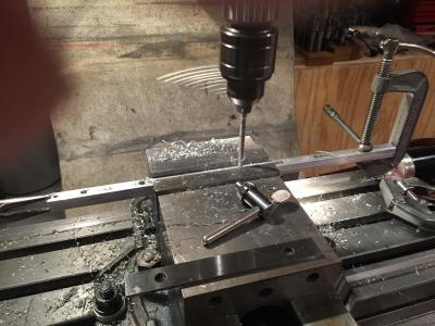
In any case, the work goes on. Last night I drilled the new alignment rails and converted the drilled bolts to vacuum line ports.
Last summer I refreshed my gearbox, and Radical sent me a new layshaft and first gear, and invited me to visit the factory when I visited London the next month. The parts didn't fit, and so I took them (old parts and new) with me to London. At the end of the tour my "guide" convened the parts manager and gearbox guru: "Blanty, you have sent the wrong gearbox parts to America, and now the customer has turned up here".
The parts guy was astonished!!
Anyway, they put their heads together and found me replacements. My gearbox is so old that it's a different series (58 series vs 72 series), so they didn't have new stock of the layshaft, but did find a workable used version. I'm afraid the next time the 'box needs more than refresh parts, I'll have to buy a new one.
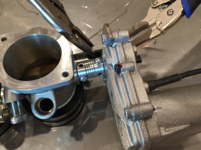
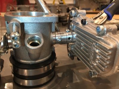
With the vacuum manifold and vacuum port problem solved, I've moved on to how the actuator will work. I found a sweet 8mm ID CNC router coupler that allows the actuator to directly drive the throttle blades. The flats on the actuator and the throttle bodies are exactly 90* apart, allowing full throttle blade. rotation from shut to fully open.
I've passed this on to Jenvey -- their design staff are reviewing it. I think it will work fine, but I always want expert advice and review.
Looks good John! This is a huge job. I am enjoying watching your progress.
Charley
Thanks Charley. I'll keep the updates coming. Summing up progress and photographing things as I go helps keep me organized and focused. 🙂
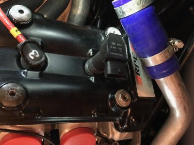
My trial ignition coil arrived today. It's from the Bosch Motorsports catalog, designated PS-T. Truth be told, it's a passenger car coil used in Alfa Romeos in the early 2000s. Most importantly: it fits, has its own internal ignitor, and calibration data is available. Now I need 7 more, plus 8 connectors. 🙂 I'll also need to add a hold-down bracket.
This looks like a very satisfying project. This is the kind of thing I love. Are you going to have to start from scratch on the calibration/maps? Or has someone done this before that is willing to share?
The sensor calibrations have all been done -- that's just a matter of patience and mastering the M1 Tune software to enter them all.
The MoTeC is like a late model manufacturer ECU -- there are no fuel maps. One fills in the basic information: fuel injector specs, engine size, fuel pressure, RPM limits, and with air temp, manifold and barometric pressure and output lambda data, the ECU works from there. Tuning is actually done in "efficiency tables", i.e., how well the air and fuel is converted to exhaust. Of course there are going to be lots of problems, and it will take a few dyno (rolling road) sessions get a good handle on the engine's efficiency.
But I agree: this is a chunky project. Lots of things to try, and lots of new stuff to learn.
While I wait for some final parts on the DBW actuator, I've turned my attention to the PWM control of the fuel pump. The OEM design is to use a return line with a mechanical regulator, and while it's simple and (mostly) reliable, it has a couple drawbacks. The first is fuel heating. As the fuel is pumped and cycled through the rails and then back to the tank, it picks up heat from the the engine and raises the fuel tank fluid temperature. The other disadvantage is that the fuel pump runs at full speed all the time. These disadvantages fade a bit when applied to a track/race car like the SR8 (with a flat-out throttle the returned fuel amount should be small, and at full throttle the fuel pump will need to be at or near full speed anyway), but there is another way of supplying the correct fuel pressure.
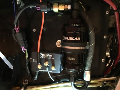
That way is to use PWM (pulse-width modulated) control of the fuel pump. I bought a new fuel pump (my 07 Radical SR8 uses a Siemens/VDO pump from a 2002 Audi TT) and sent it to my buddy Carl Casanova at VaporWorx. Carl tested the pump and tweaked his fuel pump controller to run the VDO pump at 60 psi. The controller needs input from the dedicated fuel pump sensor along with the MAP sensor (to provide fuel pressure relative to manifold pressure). The controller can maintain this pressure from idle to wide open with less than 1% delta from the target pressure.
Here's a picture of it, with most of the wiring done:
Jenvey wanted me to change the design of the DBW -- they didn't like how I'd made the actuator driver the throttle directly, rather than through a linkage. I'm a big believer in learning from experts, and Jenvey design staff has done way more DBW systems than me!
So I changed the design to align more with how they typically do it.
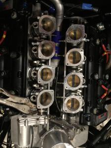
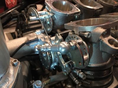
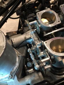
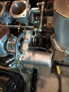
And, it's better this way. Here's a few photographs, with it all bolted in place. I need a longer rod between the actuator and the right side linkage, and Jenvey has one on the way.

